Vision Navigation Part 1: Overview of Vision Navigation
Table of Contents
- What is Vision Navigation?
- How does Vision Navigation work?
- How is Vision Navigation used?
- What are the advantages of Vision Navigation?
- What are the disadvantages of Vision Navigation?
- When do you use Vision Navigation?
- What types of Vision Navigation Techniques are there?
- Glossary
- Links, References and Jumping-off Points
What is Vision Navigation?
Vision Navigation illustration from “Object Goal Navigation using Goal-Oriented Semantic Exploration”
CREDIT: https://github.com/devendrachaplot/Object-Goal-Navigation MIT License
Vision Navigation is a blanket term that describes using optical-like raster input devices to discover your position and orientation (“pose”) and then use that position to plan, execute and monitor changes in position/pose within the environment. This usually implies planning and executing movements and steering, but can also be used as a primary or secondary localization system to monitor, update and correct the vehicle’s concept of where it is and where it’s going.
There are many types of position/pose/localization systems and sensors available. Modern vehicles and devices might use accelerometers, magnetic compasses, GPS/GNSS, IMU/INS systems, odometry, LIDAR, RADAR, passive and active trilateration and triangulation and others, each with their own strengths and weaknesses.
Autonomous robotic vehicle navigating using multiple sensors including vision-based navigation.
CREDIT: NASA/Joel Kowsky https://www.flickr.com/photos/nasahqphoto/18724437076/ CC BY-NC-ND 2.0
Vision Navigation specifically is the subset of sensing and localization that derives from using a raster-based sensor (one that can take multiple samples typically in a rectangular grid) like a camera, that senses some sort of focusable radiated energy. This is most often RGB visible light, but could also be infrared, ultraviolet, or perhaps even SAR (Synthetic Aperture RADAR) which produces a high-resolution raster image of a target.
Vision Navigation generally is concerned with the ability to take a captured raster input, and derive a position/pose localization solution from it. What is done with this localization data (path planning, execution, etc) is outside the scope of Vision-specific Navigation, and becomes a case of generalized Navigation and is not covered here.
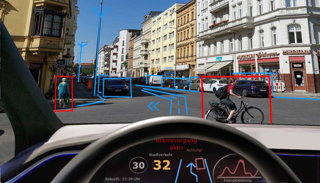
Artist’s rendition of what an autonomous vehicle sees and plans.
CREDIT: Wikimedia / Eschenzweig https://en.wikipedia.org/wiki/File:Autonomous-driving-Barcelona.jpg CC BY-SA 4.0
How does Vision Navigation work?

Vision Navigation works by computing a position+orientation localization solution based mostly on input raster data. As an analogy, in the days before smartphones and SatNav GPS units in vehicles, we might have a navigation plan to go to a restaurant in a small rural town that looks like:
- Depart from the Rustic Inn by driving down the driveway to main road. Turn right.
- Drive for about one mile to the Church with the steeple. Turn left at the church.
- Drive up the hill until you pass the lake, then turn right at the second mailbox.
All of these steps are using Visual Navigation. Neither the vehicle nor the operator knows their exact distance or direction traveled, nor do they know the exact location/coordinates of their destination or intermediate waypoints. Every maneuver is expressed in terms of actions and locations that can be measured visually without the contribution of any further instruments or sensors. If the vehicle or operator has additional information (like a map) and sensors (like a compass, speedometer, clock and/or odometer) they can also be used to supplement, cross-check and error-correct the navigation solution being executed by the Visual Navigation system, but it should be possible to get to the restaurant purely using Visual Navigation. Now, if it’s night, or foggy or a blizzard, Visual Navigation might not perform as well as you’d like and you might need to supplement it. In the tech world, supplementing multiple sources of navigation data and solutions with each other is often done with a sensor fusion system such as an Extended Kalman Filter. While navigating from the Inn to the restaurant this would be performed by your dinner companion telling you from the passenger seat that you are a terrible navigator and you obviously missed the turn by the cows.
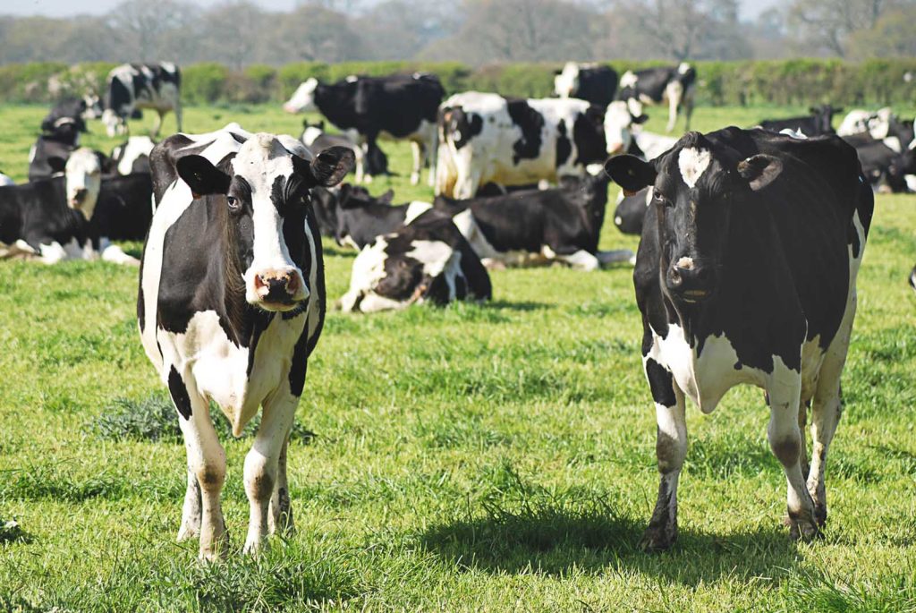
The cows you missed.
CREDIT: Monika Kubala on Unsplash, Unsplash License
In the field of robotics and unmanned systems, Vision Navigation is almost always combined with additional sensor inputs and navigation models where available, because every system has its flaws and weaknesses, and only by utilizing multiple disparate solutions can you have confidence in the accuracy and precision of your navigation solution. In manned systems, Vision Navigation can still augment the operator/pilot and other autonomous systems by assisting with tasks that can be performed visually either faster or better than autonomous subsystems or the operator/pilot. For example, while a radar or infrared system could be fooled by countermeasures like chaff or flares, a visual based system could potentially track and target an opponent aircraft, and do it more precisely and rapidly than a human pilot or Weapon Systems Officer without stealing their attention and increasing their cognitive load.
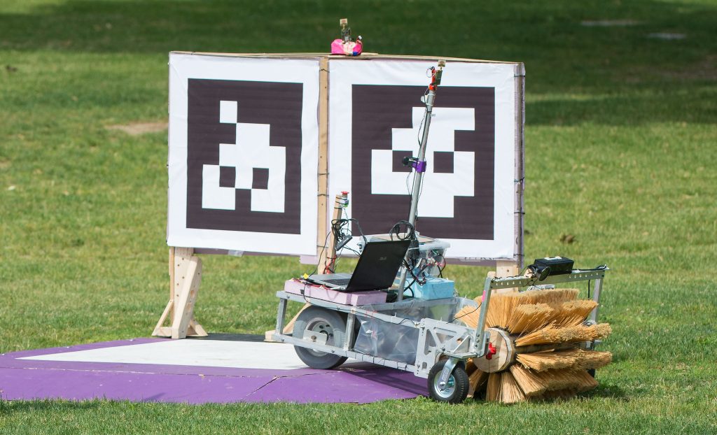
Vision Navigation can be a simple system or a very complex one, depending on the needs of the task at hand. To navigate to the restaurant, you might need to be able to have visual capability to keep the vehicle on the road, manage its speed, avoid obstacles, execute course changes, and recognize the critical landmarks (mailboxes, hills, lakes, different colored barns). A robot navigating through a factory or office might get a helping hand in the form of custom landmarks like Apriltags or Aruco markers, so it doesn’t have to recognize more organic landmarks like doors, stairs, coffee makers, water coolers, etc. In the real world, an unmanned aircraft might need to be able to spot different types of buildings from above, recognize road network shapes, or spot large regional landmarks like mountains to judge its position and orientation relative to them.
How is Vision Navigation used?
There are two phases to using Vision Navigation: Preparation and Production. In preparation, the vision Navigation is configured and possibly trained to be able to transform the raster image inputs it is expected to receive into a useable positon/orientation localization navigation solution. This may involve processing a large database of training imagery to either directly be recognized as a whole, or be recognized after some degree of abstraction and decomposition into discrete objects. Testing is usually conducted during preparation to validate that the vision navigation system can perform adequately under all expected conditions, but with data it has not previously seen (for example during training). Once the vision navigation system passes testing adequately, it can move on to production.
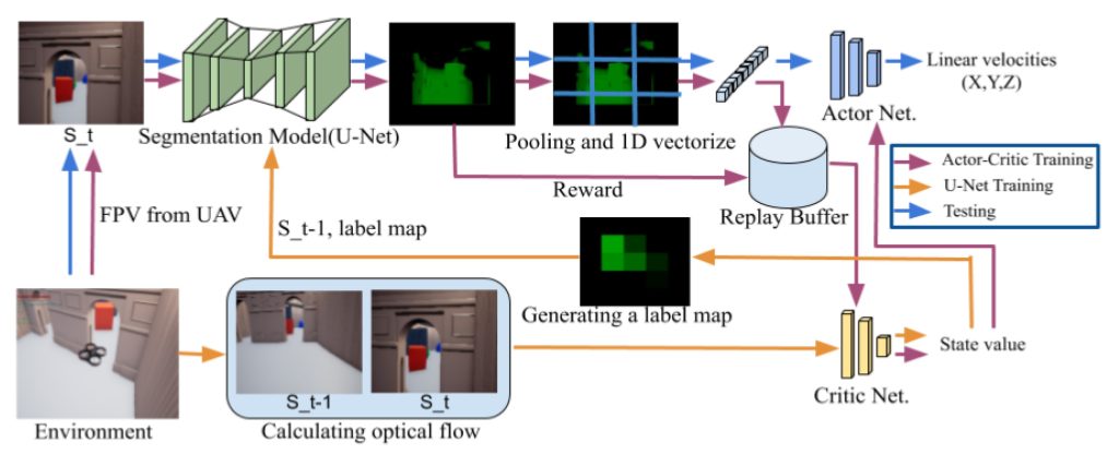
Block diagram for training and testing a drone navigation system.
CREDIT: Obstacle Avoidance Drone by Deep Reinforcement Learning and Its Racing with Human Pilot, Sang-Yun Shin, Yong-Won Kang, Yong-Guk Kim ( https://www.mdpi.com/2076-3417/9/24/5571/htm CC BY 4.0 )
In Production, the vision navigation system and its necessary supporting data are installed in the vehicle or system it will be used in, further tested for installation and operational functionality and then utilized in the real world. Many times these systems will not initially perform as well as anticipated, necessitating a trip back to preparation and further testing to improve them, possibly with the contribution of additional visual and almanac data to refine the system’s ability to localize and navigate. As vision navigation systems are utilized in the real world, the live data they ingest to make decisions can also be captured and archived, and utilized later for additional training of the core algorithm. For example, all self-driving vehicle systems such as Tesla’s Autopilot, Google Waymo’s vehicles and the open-source Comma.ai system have been capturing real-world data for years, a technique referred to as “fleet learning”, creating massive libraries of real situations that can be used to correct mistakes that earlier generations of their technology made. Tesla and Comma.ai rely almost entirely on vision navigation systems for their autonomous operation, not equipping vehicles with active emissive sensors like LIDAR, though they may utilize limited resolution RADAR or ultrasonic rangefinding sensors for lower-level planning and error prevention. Often these very accurate but expensive (e.g. LiDAR) or inconvenient (e.g. RTK) are used for creating ground/truth data to train vision against – like “training wheels”, or to aid with automated “annotation” (human annotation is expensive and often inaccurate).
In an autonomous passenger vehicle like these, vision navigation performs many simultaneous tasks. These include detection and analysis of road surface markings, detection, localization and trajectory/intent prediction of other moving objects like vehicles, detection and characterization of hazards like debris, animals and people, and recognition and interpretation of traffic control signals and signs. Each of these tasks may use a completely different vision navigation algorithm. For example, detection and identification of hazards, vehicles, signals and signs could potentially be performed by a high-performance object recognition algorithm like the YOLO (You Only Look Once) family. At the same time, a SLAM-type (Simultaneous Location And Mapping) algorithm may be used to construct a realtime model of the whole environment as perceived by the vision navigation system and extract the position and motion/trajectory of the vehicle and other moving objects within it.
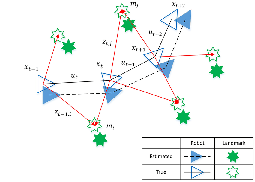
Illustration of SLAM process and Estimated Error (from A Novel FastSLAM Framework Based on 2D Lidar for Autonomous Mobile Robot )
CREDIT: Xu Lei, Bin Feng, Guiping Wang, Weiyu Liu ( https://www.researchgate.net/publication/340904235_A_Novel_FastSLAM_Framework_Based_on_2D_Lidar_for_Autonomous_Mobile_Robot CC BY )
What are the advantages of Vision Navigation?
Vision navigation is flexible in that it can operate in both absolute and relative modes.
A relative mode would be something like using a visual optical flow algorithm to measure Heading, Pitch and Roll changes versus the world as seen by the optical raster sensor. A visual odometry algorithm can estimate how fast you are moving through the surrounding world and therefore far you have moved. These operate in a relative fashion – they don’t need to know anything about the world around them, nor have any training in recognizing landmarks or understanding features to operate. They simply accept what they can see now, compare it with what they just saw a moment ago, and monitor and compute the apparent position/pose changes implied by the observed difference in the world from one frame to the next. This is often compared against and merged with similar data produced by drive odometry, and accelerometer/IMU based sensors to validate a holistic picture of the relative position/pose changes, using a technique like an Extended Kalman Filter or more modern successors. As an example, if you are walking down a typical sidewalk, you could simply look down at your feet and use the regular grid of expansion joint cracks in the concrete to get a good idea of how far you are moving and in what direction and orientation, based on where you were previously. You don’t need to know where you are or were in order to do this, but if you didn’t know where you were previously, relative visual navigation can only tell you where you’ve gone from a prior location, it won’t help you understand where that location was or where you are now within a city.
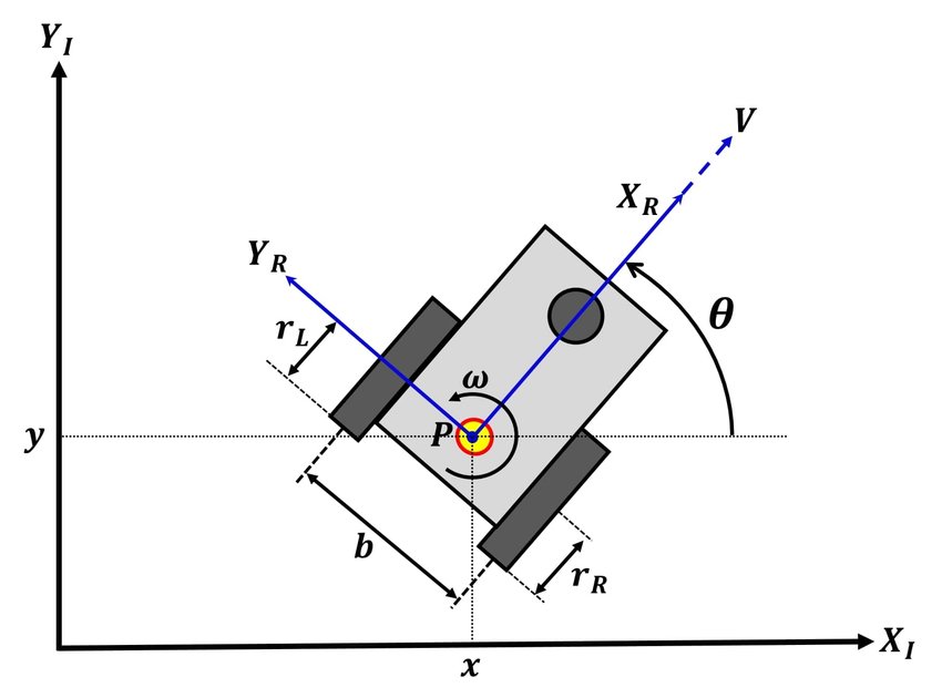
A navigating robot or vehicle can measure or estimate its relative movement and bearing.
From “Simultaneous Calibration of Odometry and Head-Eye Parameters for Mobile Robots with a Pan-Tilt Camera”
CREDIT: Nachaya Chindakham, Young-Yong Kim, Alongkorn Pirayawaraporn, Mun-Ho Jeong
( https://www.researchgate.net/publication/335317557_Simultaneous_Calibration_of_Odometry_and_Head-Eye_Parameters_for_Mobile_Robots_with_a_Pan-Tilt_Camera CC BY 4.0 )
An absolute mode visual navigation system would be one that can take a raster input and, possibly using a pre-known solution of where it believes itself to already be, construct a new assessment of where in the known “world” it is now, and what its current position is. While it might utilize a pre-conceived idea of where it was previously to narrow down the scope of its new assessment, it doesn’t have to rely on a prior localization solution. It can simply look at the current snapshot of the world around it and make a best guess as to the current solution based on its training and almanac of notable features in its landscape domain. For example, while navigating from block to block in a downtown area, if you become lost, you can usually use landmarks known to you (can you see the City Hall or Post Office or Town Square) or almanac-type landmarks such as the labeled street signs at intersections to absolutely nail down your position within the city or even within the world. If you don’t know where in the world you are, but you identify a unique landmark or set of landmarks such that you can compute where you are relative to it/them, then you know positively where you are, without having to worry about knowing where you were previously.
Relative and absolute visual navigation modes can be used together to improve the performance of both. The trick is to develop a system that can navigate in relative mode, but as soon as it receives geolocation evidence (e.g. a GPS update, or recognizing a very specific landmark), it aligns itself to a geographic map.
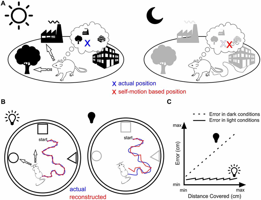
Landmark vs. motion-based navigation. From “Is there a pilot in the brain? Contribution of the self-positioning system to spatial navigation”
CREDIT: Bruno Poucet, Franck Chaillan, Bruno Truchet, Etienne Save
( https://www.researchgate.net/publication/283326479_Is_there_a_pilot_in_the_brain_Contribution_of_the_self-positioning_system_to_spatial_navigation CC BY 4.0 )
Vision navigation, and the optical sensors that drive it, can frequently be used in a passive, non-emissive mode. This means that they operate purely by focusing and interpreting captured ambient signals (like light or radio emissions) already present in the environment they are operating within. Under many circumstances, they will not need to emit their own energy (light or radio) in order to capture and analyze the reflected returning signal. Therefore vision navigation systems can frequently operate in a “stealth” role, where active emissive navigation systems like radar or lidar are inconvenient, prohibited or dangerous. Of course, not every circumstance can rely on ambient signals being present and available for capture. Night time removes the Earth’s primary illumination source, the Sun, though in many environments a vision navigation system could still operate, either by employing other environmental light sources (hardly anywhere is completely without moonlight, artificial light, etc) or by accepting the downsides of self-provided illumination via an onboard emissive signal source like a light or radio source.
Vision navigation is also frequently useable in situations where other navigation systems are inviable. There are many environments both on our planet and off it where GPS/GNSS is unavailable, denied or simply inaccessible. These could be active battlefronts with electronic warfare jamming GPS/GNSS, underwater or underground locations where GPS/GNSS signals cannot penetrate, vegetated areas with poor GPS signal or off-planet locations where GPS/GNSS will never reach.
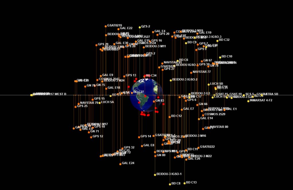
Constellation of Earth Navigation Satellites
CREDIT: Screenshotted from https://in-the-sky.org/satmap_globe.php
Vision navigation (absolute or relative) can also be viable in situations where traditional accelerometer/IMU/odometry is not feasible. Physical odometry might be very error-prone in poor-traction sand or snow, or completely impractical underwater. Rough and shock-prone situations can disrupt physical measurements used by odometry and accelerometry/gyro instruments, but optical vision navigation could still track and continuously solve for localization.
Vision Navigation database can also be customized for limited environments to optimize resources. For example, if you were constructing a vision navigation system to fly an X-Wing through the famous Trench Run from Star Wars: A New Hope, you might only bother training it with the visual features, almanac and hazards found in the Medidian Trench and not the Equatorial Trench (what, you didn’t know the Rebels attacked the Polar Meridian Trench and not the often-seen Equatorial Trench?) Similarly, if your Vision Navigation system only needs to navigate in US Cities, or maybe only in one town, or one factory, you can greatly limit the scope of data and effort that goes into the databases and training.
What are the disadvantages of Vision Navigation?
Vision Navigation systems are not perfect and there are many situations where they can not effectively operate, or are unsuitable. One obvious limit is the availability and transmissibility of the radiant energy used to reflect off of the world/scene around your sensors in order to arrive at your sensors and be detected. Sensors relying entirely on passively available radiation light sunlight or local light sources will become ineffective in completely dark environments without providing supplemental radiative/light sources with all the problems inherent in them. And some environments (fog, dust, snow, clouds, etc) will render most optical radiation transmission impossible even if you supply your own sources. Even when you can provide your own light source, in some situations this can risk unwanted exposure. Feature recognition systems and holistic localization networks can be very sensitive to lighting unless they are built with abstraction stages that can ignore it, or were trained with a sufficient variety of sample data to learn only the lighting-agnostic aspects and ignore the lighting-specific variations.
Lighting isn’t the only attribute that a Vision Navigation system needs to learn to ignore or abstract. In the large landscape of the real world, a location can look vastly different in the seasons of spring, summer, fall and winter, or even a dry versus wet summer or a cool autumn versus a long “Indian Summer”.
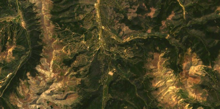
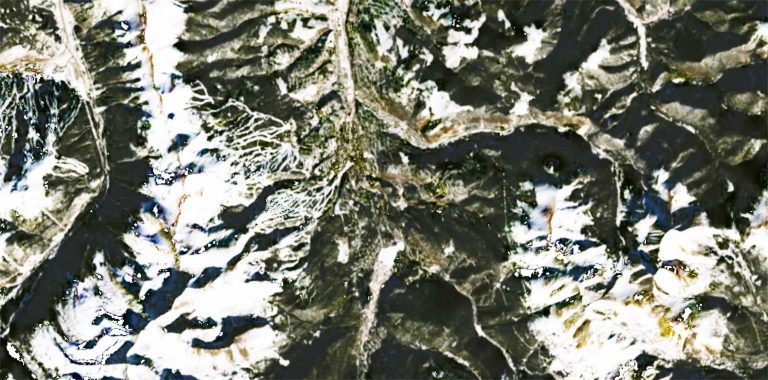
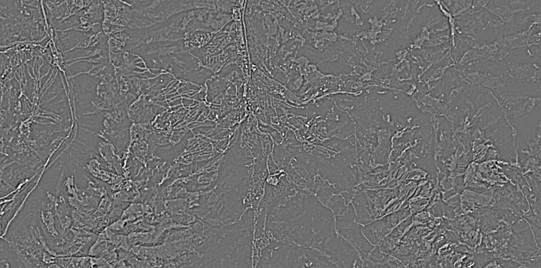
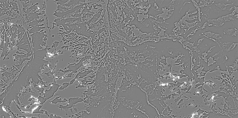
Landsat satellite RGB images showing the same mountainous scene in summer (left) and winter (right) with abstracted (hi pass, monochrome)
derivatives to enhance commonality and suppress differences.
CREDIT: The Author
As with lighting, a neural network or feature recognition system needs to either be fed abstracted enough data that these differences disappear, or extensively exposed to a great enough variety of input that it can self-develop such an abstraction, learning to recognize only the features common to all variants or representation.
Once sufficient features have been recognized, a location and pose must be computed. This can be done explicitly with Perspective-n-Point code similar to OpenCV’s solvePnP() or it can be implicitly encoded into a deep-learned neural network as part of a holistic localization stack. Both approaches can consume weighty resources.
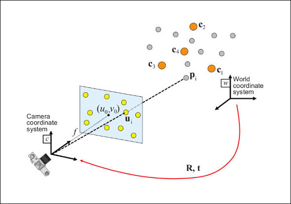
OpenCV’s solvePNP() solves for the rotation and translation that minimizes the reprojection error from 3D-2D point correspondences.
CREDIT: OpenCV Documentation ( https://docs.opencv.org/4.x/d5/d1f/calib3d_solvePnP.html Apache License 2.0 )
One of the most difficult tasks for computing localization for a Vision Navigation system is simply the magnitude and breadth of data required for training and feature almanac extraction. The quality and precision of your localization solution can never be better than the quality and resolution of the data used to train it. For example, if you want to be able to fly nap of the Earth through winding valleys in a far-off theatre, you will need to know your position with a precision of better than, for example, 30 meters. However, widely and inexpensively available global terrain model and imagery datasets such as SRTM and Landsat RGB Visible are only 30m spatial resolution. It will be very hard to derive a result with any more precision than 30m with source data such as this (gradients can help with sub-sample fit, but not significantly). The effort of acquiring, storing, processing and training with a variety of large datasets can be substantial. Even worse, some environments, such as adversarial regions or off-Earth missions, the data necessary to support training may be incredibly difficult or impossible to source. In cases like these, it may become necessary to supplement available data with simulated or procedurally enhanced data, but in doing so, you must be careful not to over-fit to fictitious data and create assumptions that the real data won’t be able to match.
When do you use Vision Navigation?
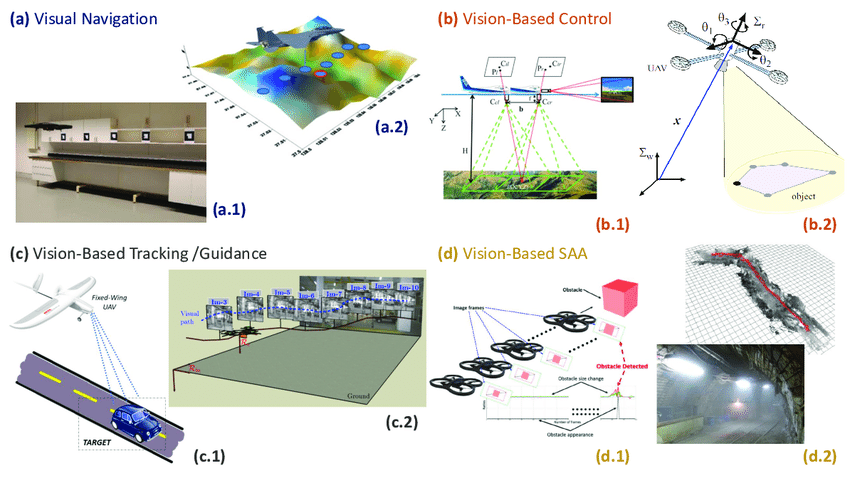
Examples of Vision Based Navigation, Control, Tracking/guidance and Sense and Avoid
CREDIT: L. M. Belmonte, R. Morales, Antonio Fernández-Caballero (“Computer Vision in Autonomous Unmanned Aerial Vehicles—A Systematic Mapping Study” https://www.researchgate.net/publication/334982493_Computer_Vision_in_Autonomous_Unmanned_Aerial_Vehicles-A_Systematic_Mapping_Study CC BY 4.0 )
Vision Navigation can be applied to numerous circumstances, as recommended by the advantages listed above. Situations must support the use of camera-like raster optical input of radiative energy, either from environmental sources (like the sun and local artificial light) or from onboard illuminators, either visual wavelength or UV/IR, or possibly raster radio energy like SAR. Visual occluders like dust, fog, rain and snow either must not be possible, or the Vision Navigation System must be able to cope with the loss of capability caused by them when present. Unavailability of traditional navigation systems like GPS/GNSS is a recommender for Vision Navigation. For Absolute mode vision navigation you must have sufficient training data of adequate quality to create or train an almanac dataset so the vision system can recognize features or environments. You will need adequate computing power both during the Preparation and Production phases to support the computational load of Vision Navigation. Vision Navigation is excellent as a primary or supplementary navigation system when traditional navigation systems will falter due to shock, vibration, signal deprivation or odometry traction/slippage issues.
What types of Vision Navigation Techniques are there?
Holistic
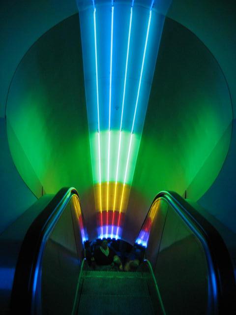
A rainbow-lit escalator where the colors change from the bottom to top.
CREDIT: Ruth Boraggina via Flickr ( https://www.flickr.com/photos/sugarpuss4ever/407938974 CC BY 2.0)
In Holistic Vision Navigation the software component (usually some kind of Deep Machine Learning Neural Network) can directly estimate position and pose from a raw or abstracted image input without creating an intermediate representation of discrete identified features. For example, imagine a long escalator traveling up an enclosed space where the paint on the walls is colored in a rainbow gradient from red at the bottom floor of the escalator to purple at the top. A holistic vision navigation system could estimate how far up the ascent it was by simply observing a sample of the continuous color change, without having to identify distinct landmark features (there are none!) and compute their spatial relationship to each other and the observer. A system like this would be very simple, needing only to acquire a small sample patch of the averaged color nearby and refer to a mapping table to associate color to position. It could be written by human hands in a simple programming language with no training or deep learning. But such a system is too simple to estimate pose, and it probably needs its own illuminator to eliminate shadowing or color casts.
A more sophisticated hand-rolled system could perhaps intentionally abstract away lighting and color/white balance complications by using a white-light self-illuminator, having a color calibration swatch or chart within the sensor’s field of view for reference, and by decomposing the RGB inputs into HSV/HSL (Hue, Saturation, Value/Lightness) colorspace, discarding the saturation and lightness values and just using the Hue to lookup against the reference table. Recovery of pose could be done by examining more than one value from within the sensor’s field of view and using a Perspective-n-Point solver to calculate the only position and pose that could have resulted in those color samples falling where they did within the camera view.
Continuing up in sophistication, the hand-rolled system above could also be constructed as a self-trained neural network via deep learning. In this scenario, a variety of sample camera images would be fed, along with their actual position and pose outputs, into a machine learning process. Care would need to be taken to have a variety of lighting conditions, and to express every possible position and pose the vision navigation system is expected to encounter in production. This system could unintentionally discover other visual phenomena that it might choose to utilize in its navigation, like paint imperfections, drywall patches, light fixtures or other landmarks. This can actually be an emergent feature.
Feature-Based
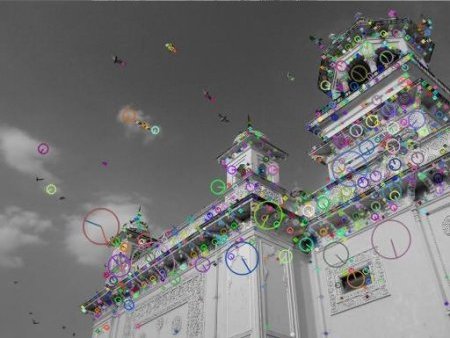
With feature-based Vision Navigation, the system doesn’t try to learn to “see” the imagery directly, rather it does a further abstraction of the imagery into discrete identified features, then tries to infer the position and pose based on the arrangement of those features in 2D space. In many cases, feature-based Vision Navigation can be superior to holistic-based architectures because it disconnects the process of feature identification from localization. In a Holistic system, if the appearance of features changes, retraining the entire vision navigation stack may be required. In a feature-based system, only the underlying feature recognizer might need updating. By way of analogy, in a holistic system that learns from actual input pixels, a red brick Post Office building landmark is very different from a tan siding Post office building. So different, that unless the vision navigation system had picked up sufficient other identifying marks (like the Post Office sign, door and window arrangement, etc) it might no longer recognize the post office as a landmark. In which case, the whole system would need retraining. Breaking apart the feature recognition and localization components allows one to be updated independently of the other. Additionally, a system capable of both capabilities is often simply larger and more performance intensive than a multi-component system.
A feature-based vision navigation system can also be composed of a neural-network-based feature identification system and a more conventional algebraic localization based on Perspective-n-Point. While many object identification systems like YOLO produce a bounding box surrounding an identified feature, other systems like BRIEF, SIFT, SURF and ORB) can be taught to focus on producing an XY point coordinate representing a consistent location within the identified feature, and potentially a scale/distance metric. This allows for computing angles and distances to known landmarks using trilateration, triangulation and/or PnP. In this case, no retraining of the localization network is needed at all if features change in position, appearance or number. Just update the feature almanac and then retrain the lower-level networks that recognize features. Going one step further, an implementation could even segregate the feature identifiers into a collection of independent recognizers, such as “Recognize Smallburg Post Office” and “Recognize Anytown Grocery Store”. Each of these could be a much smaller and more efficient neural network. An optimizing visual navigation system could then use a rough navigation solution (based on known prior location, degraded GPS/IMU solutions, etc) to load and execute only the specific landmark-recognizers that are relevant to the region at hand. This also allows for minimal and efficient regeneration of recognizers if the “Bigville Mall” is replaced with condos or the “Hill Valley Courthouse” is struck by lighting and burns. In practice, while YOLO is popular, well-known and impressive, it isn’t actually that well suited for navigation feature recognition because it is designed to generalize recognition of classes of features – “a dog”, “a post office”, “a lawyer billboard” rather than identify a particular unique specimen. Semantic segmentation networks that break a scene up into categories and extract features from the patterns are better for navigation.
In general, any neural network capable of recognizing a larger set of locations will be more complex than a smaller one. The ratio is not linear either, so deconstructing into specific smaller recognizers (for example by region) is an advantage.
Optical Flow and Visual Odometry
Optical Flow and Visual Odometry are two cases of “relative” visual navigation. They can’t tell you where you are at the moment, but if you knew where you were previously, they can help you track where you have gone since then. Optical flow is the process of studying all of the pixels in an image and comparing them with pixels from a prior frame. During this process, a ranking is computed indicating which prior pixel in the image best matches the pixel currently being studied. A 2D vector field is then constructed showing how each pixel in the image is believed to have moved from the previous frame to the current. When there is a widespread correlation in this vector field, conclusions can then be drawn about the movement of the environment in front of the Optical Flow imager.
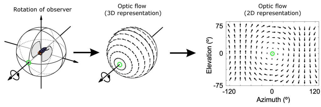
Optical flow for wide-angle vision (ex a housefly) rolling to its left.
CREDIT: Stephen J Huston,Holger G Krapp ( https://journals.plos.org/plosbiology/article/info:doi/10.1371/journal.pbio.0060173 CC BY 4.0 )
Current non-mechanical computer mice are generally based on tiny, inexpensive Optical Flow sensors that watch and compute the table surface moving underneath the mouse. A mouse only pays attention to 2D movement, and simply computes one 2D vector based (probably by averaging) on all of the input 2d vector field. However, an optical flow algorithm can in fact assess field rotation, and even non-uniform flow, where some parts of the image move or transform one way and others, another.
To use Optical flow for vehicle relative heading measurement, you need only to compute the average 2D vector flow for the whole field, and then convert that from a linear value to world-space motion/rotation knowing what you know about the field of view of the Optical Flow Sensor. If all of the pixels in the field of view seem to be moving right to left, then your sensor is probably rotating or moving left to right. It is usually possible to discriminate rotation from motion based on the cohesion of the various pixel vectors in the full vector field. In fact, a deep learning neural network can even be trained to compute this based on simulating many situations in a virtual 3d environment!
Visual Odometry is an extension of Optical Flow. It is based on the premise that as you move forward/back and side to side, different parts of the visual scene may “flow” from pixel to pixel in different amounts. During a typical move forward, objects/pixels closer to the center of the field of view will stay near the center and enlarge. Pixels representing objects nearer the edge of the field of view will move to the edge at increasing speed and also stretch/change along the lines of perspective. Visual Odometry is the process of utilizing these Optical Flow properties to infer motion and rotation purely from the pixels seen by a raster sensor, without ever understanding the meaning or identification of those pixels. Visual Odometry data can be fused with data from other sensors (like gyros/IMUs/magnetometers) to produce a combined higher-quality/accuracy/precision solution.
Continue on to Part 2 Next
Part 2a continues in our next blog post, “Implementing a Toy Vision Navigation System“.
Where do you want to Navigate your Vision today?
AlphaPixel has experience in many different forms of computer vision navigation across numerous clients and projects. Our background in GIS and mapping, telemetry, and GPS/GNSS systems is a great fit for precise vision navigation challenges. We have numerous team members able to apply their skills and expertise to solving your difficult problems, like Vision Navigation. Need help? Smack the big green button below to get in touch with us.
Glossary
- Deep Learning https://en.wikipedia.org/wiki/Deep_learning
- Extended Kalman Filter https://en.wikipedia.org/wiki/Extended_Kalman_filter
- Feature https://en.wikipedia.org/wiki/Feature_(computer_vision)
- GPS/GNSS https://en.wikipedia.org/wiki/Satellite_navigation
- IMU/INS https://en.wikipedia.org/wiki/Inertial_navigation_system
- LIDAR https://en.wikipedia.org/wiki/Lidar
- Localization https://en.wikipedia.org/wiki/Robot_navigation#top-page
- Machine Learning https://en.wikipedia.org/wiki/Machine_learning
- Neural Network https://en.wikipedia.org/wiki/Neural_network
- Odometry https://en.wikipedia.org/wiki/Odometry
- Optical Flow https://towardsdatascience.com/understanding-optical-flow-raft-accb38132fba
- PnP / Perspective-n-Point https://en.wikipedia.org/wiki/Perspective-n-Point
- Pose https://en.wikipedia.org/wiki/Pose_(computer_vision)
- SAR https://en.wikipedia.org/wiki/Synthetic-aperture_radar
- Trilateration http://wiki.gis.com/wiki/index.php/Trilateration
- Triangulation https://en.wikipedia.org/wiki/Triangulation_(surveying)
- YOLO https://towardsdatascience.com/yolo-you-only-look-once-real-time-object-detection-explained-492dc9230006
Links, References and Jumping-off Points
- https://magpi.raspberrypi.com/articles/add-navigation-to-a-low-cost-robot
- https://bigfacerobotics.wordpress.com/2015/04/24/navigation-to-a-target/
- https://www.youtube.com/watch?v=aRzqF45j5b0
- https://www.youtube.com/watch?v=zjoYTW-tLxE
- https://paperswithcode.com/task/visual-navigation
- https://arxiv.org/pdf/2108.04097.pdf
- https://www.sciencedirect.com/science/article/abs/pii/S0967066110000808
- https://www.tandfonline.com/doi/full/10.1080/10095020.2017.1420509
